Marketing Partners: contact us at feplslm@gmail.com
Introduction
The understanding on the device characteristics is the most important part of power electronics study. The line of power electronics trainers are aimed at making the study convenient and complete. The devices are connected to a well protected circuit with digitally controlled power supplies and accurate metering. A TFT colour LCD along with encoders and switches are used for user interaction to make the setup user-friendly and convenient. The user can set the control of the digital power supplies manually or use one of the auto-plot modes to plot the V-I characteristics of the device instantly.
This setup enables the user to forget about getting the circuit to work and focus on learning the intricacies of the device characteristics. The auto-plot feature enables the user see the textbook waveforms of the V-I characteristics in an instant.
The usage of proper current source power supplies for current controlled devices like SCR and TRIAC enables the user to set a constant current value. This makes it possible to find the actual trigger point of the device, which would be otherwise impossible with any other regular lab setup with a voltage source.
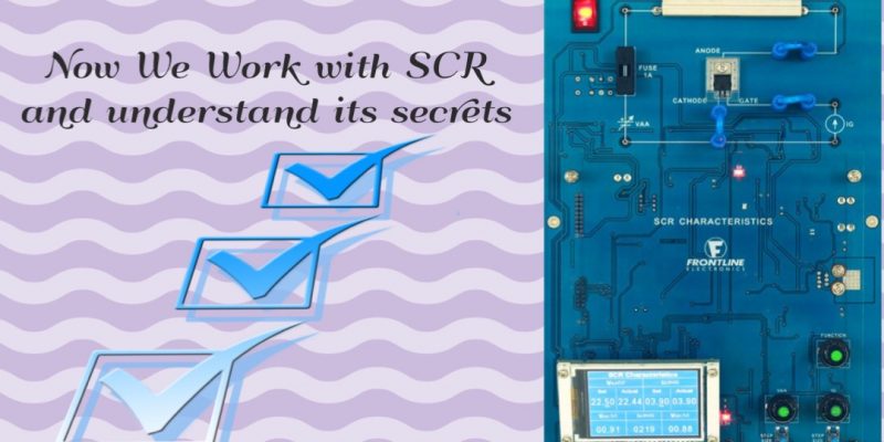
The system consists of the following:
Device Under Test – SCR.
Load resistor.
Programmable voltage source – Vaa.
Programmable voltage source – Vg.
High resolution measurements – Vaa, Vak, Vgk.
Current measurement – Ia, Ig.
Trainer User Interface
The user interface of the trainer consists of a TFT LCD to display the measurements and graphs along with encoders and switches to get inputs from the user. The trainer has multiple modes of operations meant for direct display of set and measured values and also for the automatic display of waveforms.
To power up the SCR, a programmable voltage sources Vaa and the programmable current source Ig are made available in the system.
Operating Modes of the Trainer
Measurement Mode
In the measurement mode, all power supplies are user controlled and both set and measured voltage/ current values are displayed, enabling the user to manually adjust the parameters and view measurements.
For the power supplies Vaa and Ig, the SET and ACTUAL values are displayed side by side on the LCD. The measurements Vak, Vgk, and Ia are also displayed on the LCD. The encoders and tactile switches can be used to manually adjust the power supplies and record the measurements to study the device characteristics.
Auto-Plot Mode – SCR V-I Characteristics
The V-I characteristics mode plots Vak versus Ia for user set values of Ig. When the AUTO PLOT switch is pressed, the Vaa voltage is varied from 0 to 25V automatically and the measured Vak and Ia values are plotted. Before starting this plot, user is required to set the value of Ig. A maximum of five plots can be displayed on the screen simultaneously.
The Auto-Plot modes are incorporated into the system to ensure the users, most of the time students, about the proper operations of the target device and inspires them to take up the device study with confidence and ease. The users have to generate all the plots by themselves. Auto-Plot graphs are only visual reference to them and plot values are not available to the users.