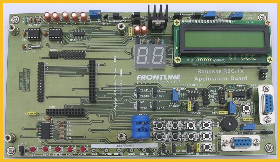
R8C1X Micon Application Board.
The R8C Evaluation Platform contains a Micon Top Board and an Application Board. The Micon board can be mounted on the base application board during study and evaluation.
The Application board carries various interfacing options like Two digits of multiplexed LED displays with BCD input, LCD module with 2 line X 16 characters, keyboard with 2X4 matrix, Push Button Switches, Point LEDs, Interrupt driving switches, Analog voltage sources, I2C bus devices like RTC and EEPROM, Onboard square wave form generator and pulse generator and etc. This wide range of peripherals enable you to study many interfacing options using R8C/1X series devices.
The hardware is supported with plenty of software examples that use these peripherals in all possible options.
Multiplexed Seven Segment LED Display Module:
This module contains 2 digits of multiplexed Common Anode Green displays with BCD input driven by the Micon. The BCD inputs (A, B, C and D) of multiplexed displays and the digit selection control lines can be connected to port 0 of the Micon through the a buffer IC 74LS245 (U5) by connecting the pins 3 & 4 of jumper, JP5.

The BCD input is converted into seven segment format using a BCD to seven segment decoder IC 74LS47.The segment output from the decoder is connected to the display through current limiting resistors. The digit select lines are connected to the port lines using PNP transistors, BC557.
LCD Module with 2 lines X 16 Characters:
This is a standard interfacing facility available to connect LCD modules. This is common to many modules up to 4 lines X 20 characters. The LCM is interfaced with the Micon using 4 bit bus. To interface a LCD module in 4 bit mode, 6 port lines are required: 4 data lines, D4 to D7, Enable line, E and Command/Data selection line, RS. The Read/Write selection, R/W line is connected to ground to select write operations always. The LCM control and data lines are connected to the port 0 of the
Micon.

A provision is also available for LCM's contrast adjustment using R3 trimpot which is kept near by the LCM.
The LCM is connected to the Micon thorugh a buffer IC 74LS245(U2). The LCD can selected by connecting the pins 1 and 2 of jumper JP5.
Four Numbers of Point LEDs and Buzzer:
The Application board contains 4 red color simple point LEDs connected with Micon using the buffer 74LS245.

The buzzer can be connected to the port line P31/TZOUT through the buffer by connecting the pins 1 & 2 of jumper, JP19. The LEDs are connected to the port lines P17(LED2), P30(LED3), P31(LED4) and P32(LED5) through buffer.
The activating level of the LED is high (1 level). Care is taken to connect the timer/counter output lines to points LEDs. This option facilitates the study of timers.
Keypad with 2 X 4 Matrix:
8 numbers of micro switches are configured as a matrix of size 2X4 to function as a keypad in the Application board.

The column and row lines of this key matrix is connected to the port lines: P16, P45, P10, P11, P12 and P13.
The matrix keyboard can be either configured as matrix keyboard or as 4 numbers of push button switches to give pulses to keyboard interrupts KI0 to KI3.
To configure as matrix keyboard, connect the pins 2 & 3 of jumpers JP3 and JP4. This will connect the port lines P16 and P45 to the keyboard rows.
When the port lines P16 and P45 are connected to the row lines of matrix keyboard they should be disconnected from the I2C devices because both the modules use same port lines. This can be done by using the jumpers JP12 and JP13.
The switches SW2 to SW5 or SW6 to SW9 can be configured as push button switches to give pulse intput to the keyboard interrupts by connecting the pins pin1 & 2 of JP3 or JP4 respectively. This will connect ground level to the of micro switches.
Push Button Switch to Control Interrupt:
The Application board contains a Push Button Switch to test interrupt line INT3 and give clock to Timer C. The Micon board has three push button switches to test interrupt lines INT0, INT1 and INT2.

Push button switch(SW1) can also be used to give pulse to the Timer C.
Jumper JP2 is provided to connect the port line P33(INT3) to the push button switch SW1. By connecting the pins 1 & 2 of JP2, the switch SW2 can be connected to the port line P33.
When the swicth SW2 is pressed, it will give a low level signal to the interrupt line.
Analog Voltage Source to Experiment with ADC:
One Analog input voltage sources is made available in the application board to experiment with ADC part of the Micon. The analog source can be connected to the channel AN6 input of the Micon device through jumper, JP10.
The Ground, Analog input AN6 are terminated as test points for measuring purpose.
The analog source can be connected to the analog input by connecting the pins 1 & 2 of jumper JP10.
When the analog source is connected to the analog input AN6, the outputs of LDR and thermister modules should be disconnected from AN6.
I2C Devices RTC and EEPROM:
The Application board contains facility to interface I2C devices like RTC, PCF8583 and EEPROM, AT24C08. These I2C devices can be connected with the port lines P16 and P45 of Micon.
I2C RTC Device:
The Philips I2C RTC, PCF 8583 can be connected to the I2C bus of Micon as shown
here.

This RTC device has 256 bytes of RAM along with real time clock function. Battery backup facility is available onboard to protect RTC and memory contents in case of power failure.
The SDA and SCL lines of the RTC device can be connected to P45 and P16 of Micon through jumpers JP13 and JP12.
The level to the address line A0 of the RTC is set to 0.

The EEPROM has 1K bytes capacity. The address lines A0, A1 and A2 are set to 1level.
The SDA and SCL lines can be connected to the Micon port lines P45 and P16 through JP13 and JP12.
You can replace this low end EEPROM with any higher capacity device up to 64K bytes without any hitch.
While connecting I2C Devices to the micon, disconnect the port lines from keyboard matrix row lines.
Square Wave Form Generator:
Application board has built in square waveform generator with two-frequency ranges. One is low frequency range (18 HZ to 2KHZ) and the other is high range (2KHZ to 30KHZ). The range can be selected using jumper JP6. The range is marked as ôHIö and ôLOö.
The square wave generator is built using CD40106 Schmitt trigger IC. The frequency can be varied by using the variable trimpot (R18).

This square waveform generator can be used to study the timer functions of the Micon.
On Board Variable Pulse Width Pulse Generator:
Application board has onboard variable pulse width generator. The IC 74LS123
is used for pulse generation. Out of the two available channels, one channel is
used and both Q output and complement of Q output can be connected to the port lines of Micon.
To give the trigger signal to the mono shot, a push button switch (SW10) is used and it is marked as ôTriggerö. The width of the pulse can be varied using variable trimpot (R20).

The pulse width can be varied from 33 Microseconds to 33 milliseconds approximately. To get a pulse output, press the SW10 (TRIGGER) button.
This can be used to study the timer functions of the Micon. The outputs of the pulse generator can be connected to timer input lines or interrupt lines of the
Micon.
|