R8C1X Micon Top Board
The R8C Evaluation Platform contains a Micon Top Board and an Application Board. The Micon board can be mounted on the base application board during study and evaluation.
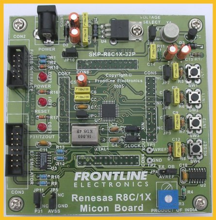
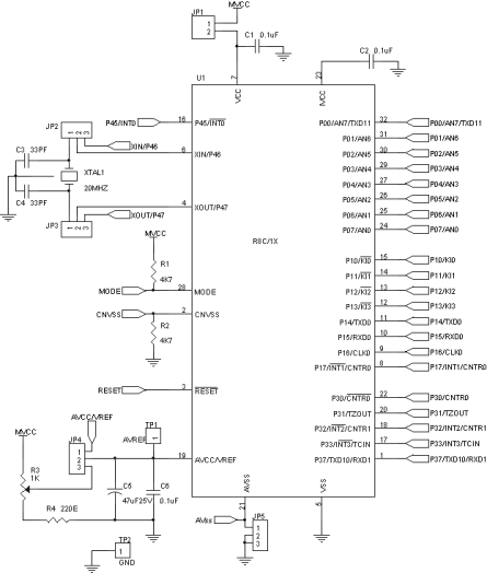
Micon:
The Micon is placed in the centre of the
Micon board. The port lines are terminated in 4 connectors, CON4, CON5, CON6 and
CON7 to connect the application board. A facility is provided via jumper JP1 to
measure the current consumed by the Micon. To measure the current, open the
jumper JP1 and connect an ammeter across the jumper. After measuring the current
short the jumper JP1 for proper operation.
Clock Circuit:
A crystal and two capacitors are connected to the oscillator pins (XIN and XOUT) of the Micon to give clock pulses for proper operation of the Micon. The crystal value depends on the Micon and it may be either 16Mhz or 20 Mhz.
Two jumpers JP2 and JP3 are provided to connect or disconnect the clock circuit to Micon pins.
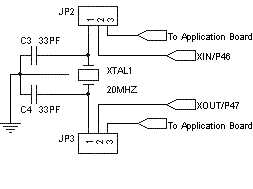
The crystal may be disconnected from the Micon pins when the internal ring oscillator is selected. When internal ring oscillator is used, the Xin and Xout lines can be used as I/O lines.
Reset Circuit:
The reset circuit consists of a resistor and a capacitor network, a push button switch,
Schmitt trigger IC and an AND gate as shown below:

The RC circuit is connected to the input of the schimtt trigger circuit and the output is connected to the reset pin of the micon through an AND gate. The reset from the FoUSB, E7 emulator and from the application board are ANDed together to give a reset signal to the Micon. A push button switch is also provided to give manual reset.
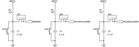
Push Button Switches:
The micon board has three push button switches connected to the interrupt lines INT0, INT1 and INT2. These switches can be connected or disconnected from the micon pins using jumpers JP7, JP8 and JP9. The swicthes will give low output when activated.
On Board 5V and 3V Regulator:
The micon board has on board regulator circuit for both 5 Volts and 3 Volts for the proper operation of Micon.
The 5 volts regulator is built around 7805 device as shown below:
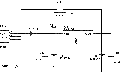
A provision is also provided to by pass this regulator using jumper JP10. This jumper helps to connect regulated 5V directly to the board.
The 5 volts is then converted into 3 volts using two transistors as shown below:

For the protection against high voltage noise, a 5.1Volts TVS is connected across the +5V and ground lines.
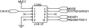
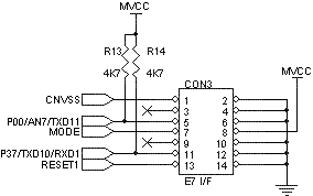
FoUSB and E7 Emulator Interfaces:
For debugging purpose, two types of interfaces are provided. One is FoUSB interface and the other is E7 emulator.
The FoUSB interface is terminated in a 10 pin FRC connector as shown below:
The E7 emulator lines are terminated in a 14 pin FRC connector.
Onboard Analog Voltage Source:
A variable analog voltage source is provided on board to give an analog reference voltage to AVREF pin of
Micon.
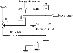
The reference can be set by varing the trimpot R3. Provision is also provided to give external reference instead of the on board reference using jumper JP4.
Test points for this reference pin and ground are provided for your convenience.
LED Indicators:
Three point LEDs are provided to give indication for the power, reset and the level of port P31.

The LED3 is connected/disconnected to P31 by using jumper JP11.
|