Topview Simulator
Simulation Facilities
I/O lines : During program execution, inputs can be set and you can watch output lines
for desired results.

- Interrupt lines (both level and edge triggering) are also supported.
- Clock pulses can be simulated for Timers/Counters 0,1 and 2.
- For the AT89CX051 devices, Onchip Analog Comparator can also be simulated. Facility is
there to give variable inputs to the comparator.
- For AT89S53, AT89S8252 devices, Watch dog timer is also be simulated.
- All modes of Serial port are simulated.
Topview Simulator simulates all possible four modes of the serial port including Multiprocessing
Communication. There is a facility that enables you to send a test data byte out of the
serial port and you can view that data going out of the serial port. Similarly you can
view the data bytes received at the serial port.
- Separate buffers of size 256 bytes are provided for capturing both transmitted and
received data bytes.

- These buffers can be saved separately for verification.
- During execution, data transmitted out of TXD line is captured and displayed
continuously for your verification.
- Similar facility is available to monitor and accumulate data from RXD line.
- There is another serial port made available to simulate external host serial port. Using
this facility you can make sure serial port of your target hardware works fine with a host
computer. This can substitute personal computer's serial port and enables you to test and
verify the serial port of the target design.
- The serial port sports the facility to send / receive data with the target hardware. you
can either manually key in test data or you can send a data file through this simulated
host serial port.
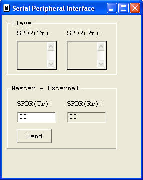
- Internal SPI module of AT89S8252 device can be simulated. An exclusive dialog box gives
the facility for this.
External peripheral modules.
External peripheral modules can also be simulated. These modules can be connected to
any available I/O lines. This should assist the user to develop and complete the project
without any real target hardware.
LED Modules.
Plain Point LEDs.
- Color of LEDs. Red / Green can be defined.
- A maximum of 32 point LEDs can be graphically simulated.
- Activation level (either 1 or 0) can be defined.
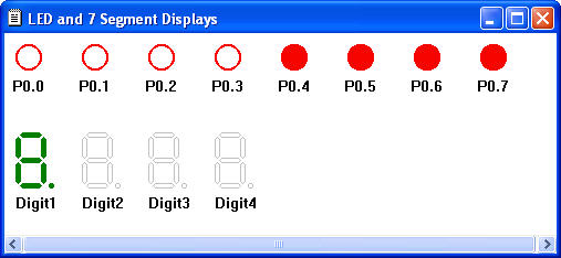
Seven Segment Displays
- 16 Digits of Seven Segment displays are graphically represented.
- Choice of display colors (Red/Green).
- Select Common Anode/Cathode displays.
- Seven Segment displays can be connected in any one of the following configurations:
- Non-Multiplexed displays with BCD inputs.
- Non-Multiplexed displays with Seven Segment Code inputs.
- Multiplexed displays with BCD inputs.
- Multiplexed displays with Seven Segment Code inputs.
- Multiplexed displays with BCD inputs using external multiplexer.
- Multiplexed displays with Seven Segment Code inputs using external multiplexer (upto 4
to 16 digits)

Maximum number of digits is defined by the configuration of the display module and the
available port lines. There is no restriction on the port lines. Displays can be connected
to available port lines of the microcontroller.

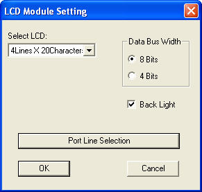
LCD Module
The simulator gives actual and exact graphical view of the LCD modules similar to real
life displays.
- Supported LCD modules: 1X16, 2X16, 4X16 and 4X20.

- Either 4 bit or 8 bit interface option can be selected.
- Facility to select the Back light of the LCD module.
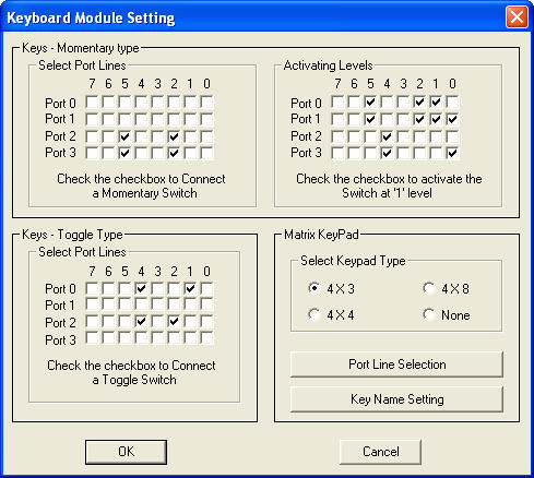
Keyboard Module
- A maximum of 32 Momentary ON type keys can be simulated.
- Active level can be selected (0 - 1 - 0 or 1 - 0 - 1)
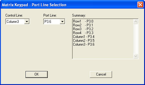
- Key matrices of type 4X3, 4X4 and 4X8 can be simulated.
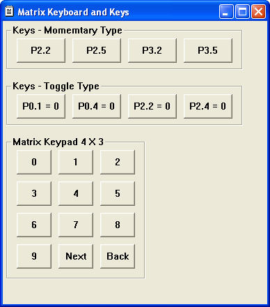
- Also toggle switches can be simulated. Maximum is 32. Key matrix, toggle switches can be connected to any port lines as per your wish list.
I2C Module
Complete external interface for two popular I2C
devices can be selected: I2C RTC, I2C EEPROM.
Devices that can be simulated :
I2C RTC : Philips RTC - PCF 8583.
I2C EEPROM : AT24C01, AT24C02, AT24C04, AT24C08 and AT24C16.
The address lines, A0, A1 and A2 can be selected according to the device.
The device can be connected with any available I/O lines.
For EEPROM devices, write protect option can be enabled.
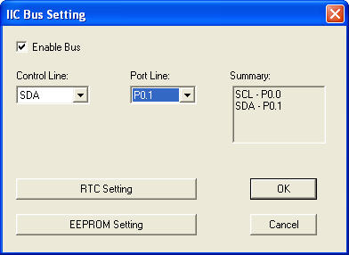
When the write protection is enabled, the contents of the device will be displayed in
different colour to indicate that the device is operating in ` Write Protect ` mode.
Special feature of I2C RTC simulation : You can use your computer's RTC
timings as reference during RTC simulation.
Benefit: Handy feature when designing time dependent projects.
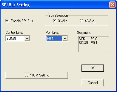
SPI Modules
All possible types of external SPI modules can be simulated and can be interfaced with
any available I/O lines of the microcontroller.
- Either 3 or 4 wire configuration can be chosen.
- Any one of the EEPROM devices can be selected:
- AT 25010, AT 25020 and AT 25040 of Atmel.
- Write protection options can be enabled.
Both I2C and SPI EEPROM devices are simulated taking into account time
required for data write cycle. This cycle may take upto about 10 milliseconds. You can't
write any command or data into or read from the device until the write cycle comes to an
end except when reading device status.
|
